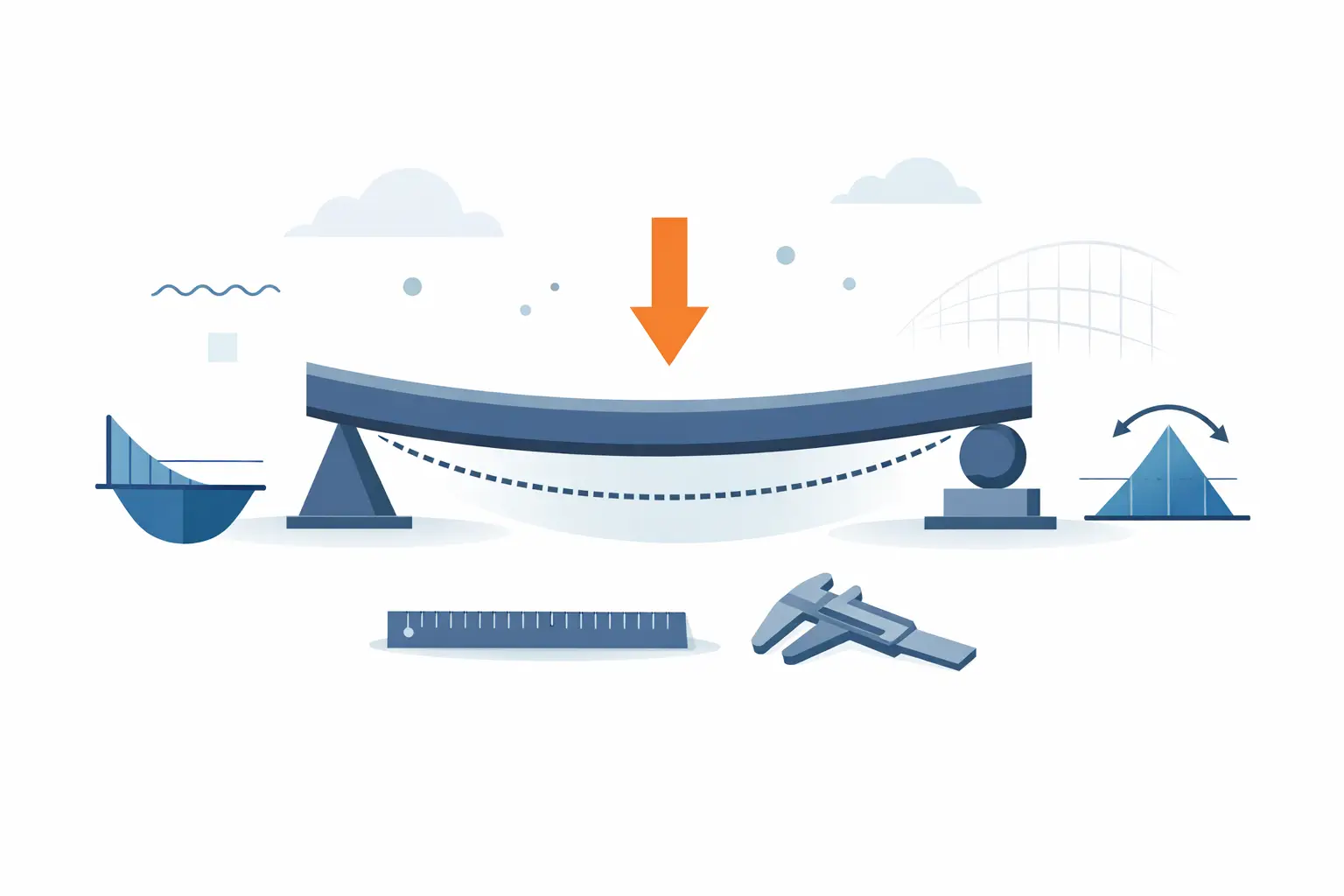
A beam can satisfy a bending-strength check and still be unacceptable in service. Excessive vertical movement can crack finishes, disrupt alignment, affect drainage falls, or simply make a floor feel uncomfortable. This beam deflection example shows how to calculate mid-span deflection for a simply supported steel beam under a uniformly distributed load, then document the assumptions and result clearly enough for another engineer to review.
The calculation uses SI units throughout. The same workflow applies to timber, aluminium, concrete, or composite members, but the stiffness value, loading model, support conditions, and applicable deflection limits must reflect the actual design case.
Beam deflection example: simply supported beam
Consider a simply supported steel beam carrying a uniformly distributed service load over its full span. The beam supports a secondary floor zone, so the deflection check is assessed at serviceability rather than at ultimate limit state.
Use the following input values:
| Parameter | Symbol | Value | |---|---:|---:| | Clear span | L | 4.80 m | | Uniformly distributed service load | w | 6.50 kN/m | | Young's modulus for steel | E | 200 GPa | | Second moment of area about the major axis | I | 8.40 × 10⁻⁶ m⁴ | | Assumed deflection limit | L/250 | 19.2 mm |
The load should include the actions relevant to the serviceability combination being checked. Depending on the design standard and project requirements, that may mean permanent actions plus an appropriate proportion of imposed, snow, wind, equipment, or partition loads. Do not substitute a factored ultimate design load into a serviceability deflection equation unless the project requirement explicitly calls for it.
For a simply supported beam with a full-span uniformly distributed load, the maximum deflection occurs at mid-span and is:
$$\delta_{max} = \frac{5wL^4}{384EI}$$
Before substituting values, convert every term into a consistent unit system. This is where otherwise sound calculations often fail. Here, the distributed load is converted from kilonewtons per metre to newtons per metre:
$$w = 6.50\ \text{kN/m} = 6,500\ \text{N/m}$$
Young's modulus is converted from gigapascals to newtons per square metre:
$$E = 200\ \text{GPa} = 200 \times 10^9\ \text{N/m}^2$$
Substituting the values gives:
$$\delta_{max} = \frac{5(6,500)(4.80)^4}{384(200 \times 10^9)(8.40 \times 10^{-6})}$$
$$\delta_{max} = 0.0267\ \text{m}$$
$$\delta_{max} = 26.7\ \text{mm}$$
The calculated deflection is 26.7 mm. The assumed limit is:
$$\frac{L}{250} = \frac{4,800}{250} = 19.2\ \text{mm}$$
Because 26.7 mm exceeds 19.2 mm, this beam does not meet the assumed serviceability criterion. The utilisation based on deflection alone is:
$$\frac{26.7}{19.2} = 1.39$$
In practical terms, the predicted movement is about 39% above the selected limit.
What this result does and does not prove
The result identifies a serviceability issue for this particular loading and support model. It does not establish that the beam is unsafe. Deflection and bending resistance are separate checks, and a member may pass one while failing the other.
A basic bending check provides useful context. For the same uniformly distributed load, maximum bending moment is:
$$M_{max} = \frac{wL^2}{8}$$
$$M_{max} = \frac{6.50(4.80)^2}{8} = 18.7\ \text{kNm}$$
That moment must be checked against the member's design bending resistance using the applicable material grade, section classification, lateral restraint condition, and design standard. Shear, bearing at supports, web buckling, lateral torsional buckling, connections, vibration, fire design, and local stability may also govern. A deflection calculation should sit within a complete member design process, not replace it.
The selected limit also needs engineering judgement. L/250 is a common preliminary benchmark, but it is not a universal requirement. A roof supporting brittle finishes may require a more restrictive criterion. A beam with no sensitive finishes may permit more movement. Long-term deflection can be especially significant for timber and reinforced concrete, where creep, moisture behaviour, cracking, and construction sequence affect stiffness over time.
Why the fourth power of span matters
The span term is raised to the fourth power in the deflection equation. This makes span changes disproportionately influential. If the span increases by 10%, deflection increases by approximately 46%, assuming all other values remain unchanged.
That relationship explains why increasing beam depth is often a more efficient solution than modestly increasing material grade. The second moment of area, I, is a measure of geometric stiffness. For many common beam shapes, increasing section depth substantially increases I and therefore reduces deflection. A heavier section is not automatically a stiffer section if the additional material does not increase depth effectively.
For this example, several design responses are possible. The engineer might select a deeper beam with a larger second moment of area, reduce the span by introducing an intermediate support, reduce permanent load through a lighter floor build-up, or revise the framing arrangement so tributary width is reduced. The right option depends on fabrication constraints, headroom, cost, connection detailing, and architectural coordination.
Check the boundary conditions before trusting the formula
The formula used above assumes ideal simple supports. Real connections may provide some rotational restraint, but relying on that restraint without a justified analysis can understate deflection. Conversely, a cantilever, fixed-ended beam, propped member, or continuous beam has a different deflection relationship and different critical locations.
The loading arrangement matters just as much. A point load at mid-span has a different equation from a uniformly distributed load. So does a partial-length load, an eccentric line load, or several discrete plant loads. If multiple actions are present, calculate their deflections separately and combine them only where linear elastic superposition is valid.
The value of I must correspond to the bending axis and the actual section orientation. For an asymmetric section or a member subject to biaxial bending, one scalar major-axis calculation may not be sufficient. Likewise, a composite beam should not be assigned transformed-section stiffness unless composite action, shear transfer, and construction stage have been properly considered.
Turning the calculation into a reviewable record
A useful calculation sheet does more than display 26.7 mm. It makes the reasoning visible. Record the beam identifier and location, sketch the support and load arrangement, state whether the load is a serviceability combination, identify the source of section properties, and write the acceptance criterion beside the result.
Unit-aware mathematics is particularly valuable for this type of work. It allows the worksheet to retain inputs in convenient engineering units while checking that the equation resolves to a length. A load entered in kN/m, a span entered in metres, and a modulus entered in GPa can be converted consistently rather than relying on hidden factors of 1,000 or 1,000,000.
A reusable worksheet can also separate inputs from derived values. Put span, load, material modulus, section property, and limit near the top. Below them, show the governing equation, intermediate conversions, calculated deflection, allowable deflection, and pass or fail status. This structure makes later revisions faster: when a span changes during coordination, the impact is immediately visible and the technical record remains intact.
Calculeaf is suited to this workflow because the formula, unit-aware inputs, explanatory notes, beam sketch, and final design check can remain in one readable technical document rather than being spread across undocumented spreadsheet cells.
Common errors in a beam deflection calculation
The most frequent mistake is inconsistent units. Combining kN/m with E in N/mm² and I in mm⁴ can produce a numerically plausible but incorrect answer. Choose one coherent system, or use a unit-aware worksheet that exposes conversions.
Another common error is using the wrong load case. Strength combinations and serviceability combinations serve different purposes. Deflection limits generally relate to in-service performance, so the load combination must match the relevant standard and specification.
Finally, do not confuse gross section stiffness with effective stiffness. This distinction is especially important for reinforced concrete, timber, built-up members, and members with partial composite action. The correct stiffness may depend on cracking, creep, connection slip, duration of loading, or restraint assumptions.
A deflection result becomes useful when it leads to a traceable design decision. State the model, preserve the units, compare the result with a justified criterion, and leave enough context for the next engineer to understand why the beam was accepted, revised, or escalated for further analysis.