RC Low-Pass Filter Cutoff Frequency
RC Low-Pass Filter Cutoff Frequency
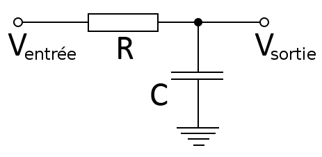
A single resistor and capacitor in series form the simplest possible low-pass filter: signals well below the cutoff frequency pass through largely unattenuated, while signals above it are increasingly rolled off. The cutoff frequency is set purely by the resistor and capacitor values chosen.This RC pair shows up everywhere from anti-aliasing filters ahead of an ADC to simple noise suppression on a sensor line, and picking R and C to land the cutoff at the right frequency is often the entire filter design task for this class of problem.
The cutoff frequency is f_c = 1/(2π·R·C), the reciprocal of two pi times the resistance-capacitance time constant. where R is the filter resistance and C is the filter capacitance.
Inputs
R_f2 := 10 kOhm=10000 Ω
C_f := 100 nF=1e-07 A^2·s^4/kg/m^2
The RC time constant sets how quickly the capacitor can respond to changing input, and its reciprocal (scaled by 2π) gives the frequency at which the filter’s output has dropped to 70.7% of the input — the standard cutoff definition.
f_c := 1/(2·pi·R_f2·C_f)=159.15 Hz
Results
A cutoff near 159 Hz from a 10 kΩ resistor and 100 nF capacitor is a common combination for audio-band noise filtering. Doubling either R or C halves the cutoff frequency, so fine-tuning the corner frequency is simply a matter of adjusting one of these two readily available component values.
Assumptions & limitations
- Ideal, lossless resistor and capacitor (no ESR or parasitic inductance).
- Single-pole filter; roll-off is a gradual -20 dB/decade above cutoff, not a sharp cutoff.
- Driven by a low-impedance source and feeding a high-impedance load.