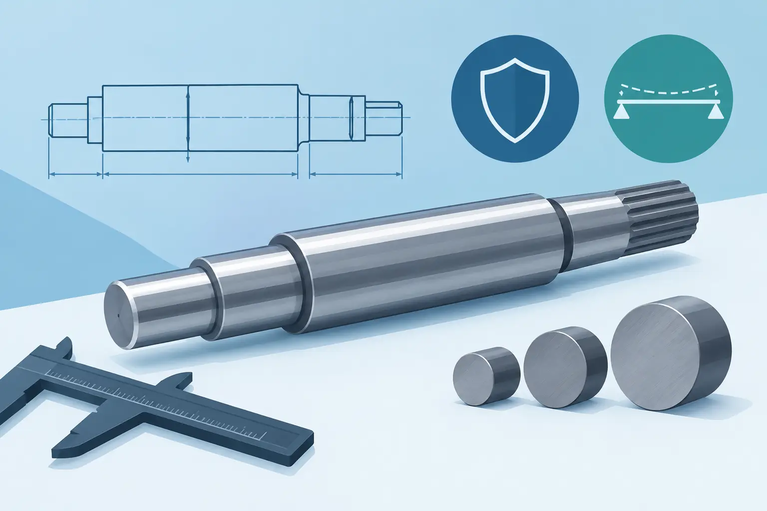
A shaft that survives a static torque check can still fail early from fatigue, deflect enough to damage a seal, or pass through a critical speed during normal operation. That is why knowing how to size shafts means treating diameter as the result of several connected design checks, not a single torsion equation.
For most rotating machinery, begin with the transmitted power and speed, then establish the actual loading arrangement. Size an initial shaft diameter for combined bending and torsion, refine it for fatigue and stiffness, and finally verify dynamic behaviour, features, bearings, and manufacturability. Keep each assumption visible. A shaft calculation is far easier to review when its load cases, material data, stress concentrations, and acceptance criteria sit alongside the equations.
Define the shaft duty before selecting a diameter
A useful calculation starts with the shaft layout: bearing locations, gears, pulleys, couplings, overhung masses, and every point where force or torque enters the shaft. A free-body diagram is not optional. It determines the bending moment distribution, which often governs shaft sizing more than nominal torque.
Calculate torque from power and rotational speed where these are known:
`T = 9550 P / n`
where `T` is torque in N·m, `P` is power in kW, and `n` is rotational speed in rpm. For variable-speed drives, use the maximum credible torque rather than only the rated condition. Starting torque, braking torque, jam conditions, and torque reversals may be more severe than steady operation.
For gear-driven shafts, derive radial, tangential, and axial gear forces from the transmitted torque and gear geometry. For belt and chain drives, include the resultant of belt or chain tensions. These forces create reactions at the bearings and bending moments along the shaft. A compact layout with bearings close to load application points can reduce bending substantially, but it may introduce assembly or maintenance constraints.
Define load cases explicitly. Typical cases include normal running, start-up, emergency stop, maximum external load, and any reversed or fluctuating duty. If the shaft operates in a safety-critical or regulated application, the applicable design code should set the required combinations, factors, and material allowables.
How to size shafts for combined loading
A solid circular shaft is commonly used as the initial design basis. Under torsion alone, the maximum nominal shear stress is:
`τ = 16T / (πd³)`
Under bending alone, the maximum nominal normal stress is:
`σ = 32M / (πd³)`
where `M` is the local bending moment and `d` is shaft diameter. The cubic relationship matters: a modest increase in diameter produces a significant reduction in nominal stress.
Real shafts are usually subject to both bending and torsion. For a ductile material under static loading, a common preliminary check uses von Mises equivalent stress:
`σeq = √(σ² + 3τ²)`
Compare `σeq` with an allowable stress derived from yield strength and the selected design factor. This gives an efficient first diameter, but it is not sufficient for a shaft with keyways, shoulders, repeated bending, or a long service life.
An equivalent torque form is also widely used for early sizing:
`Te = √[(Kb M)² + (Kt T)²]`
Here, `Kb` and `Kt` can represent bending and torsional load factors where the selected design method permits them. Do not apply factors from different standards or textbook methods without checking what they represent. Some include service effects, some address shock, and others are intended for fatigue treatment. Stacking them indiscriminately can produce a number that appears conservative but has no clear engineering basis.
Hollow shafts deserve consideration when weight, rotational inertia, or material use matters. For a hollow shaft, strength and stiffness depend on both outside diameter and bore diameter. A hollow section can provide favourable torsional performance for its mass, but the bore reduces the margin available at local features and may complicate machining, inspection, or corrosion protection.
Treat fatigue and local features as primary checks
Most shaft failures initiate at a feature, not in smooth material at the location of maximum nominal stress. Keyways, splines, circlip grooves, cross-holes, threads, shrink-fit edges, and sharp diameter changes all raise local stress. In a rotating shaft carrying a stationary transverse load, the material at the surface sees fully reversed bending stress every revolution. That makes fatigue performance central to the design.
Use theoretical stress concentration factors, then convert them to fatigue stress concentration factors using the material notch sensitivity and the feature geometry. Apply the appropriate factor separately to bending and torsion. Surface finish, size, temperature, corrosion, residual stress, and reliability can all reduce the usable endurance strength.
A practical fatigue check separates alternating and mean stress components. The bending stress may be largely alternating, while transmitted torque may create a steady mean shear stress. Where torque fluctuates or reverses, it also contributes an alternating component. Convert the combined stress state using a recognised method, then assess it against a fatigue criterion such as Goodman, Gerber, or Soderberg, according to the project requirement.
The selection depends on the consequence of failure and the certainty of inputs. Goodman is commonly used as a pragmatic linear criterion. Soderberg is more conservative because it references yield strength for the mean-stress limit. Gerber can be appropriate for ductile metals when a less conservative parabolic relationship is justified. The right answer is not simply the highest calculated safety factor. It is the result that matches the duty, material data quality, and governing design standard.
Geometry can improve fatigue life more effectively than increasing the whole shaft diameter. Use generous shoulder fillets where assembly permits, provide suitable relief at ground transitions, avoid abrupt section changes, and place keyways away from the highest bending moment where possible. Specify surface finish realistically. A polished laboratory specimen and a turned production shaft do not have the same endurance behaviour.
Check stiffness, deflection and rotation
Strength determines whether the shaft yields or fractures. Stiffness determines whether the machine works properly. A shaft that meets stress limits may still allow excessive gear misalignment, belt tracking error, seal wear, bearing edge loading, or vibration.
Calculate shaft deflection from the applied transverse loads and the flexural rigidity `EI`, where `E` is Young's modulus and `I` is the second moment of area. For a solid round shaft:
`I = πd⁴ / 64`
Calculate angular twist from torque, shaft length, shear modulus, and polar second moment of area. For a solid round shaft:
`J = πd⁴ / 32`
and:
`θ = TL / (JG)`
The fourth-power diameter relationship is especially valuable here. A small diameter increase can sharply improve deflection and torsional stiffness. This can justify a larger shaft even where stress calculations suggest otherwise.
Allowable deflection and slope depend on the components supported. Precision gears, mechanical seals, and high-speed rolling-element bearings can impose much tighter requirements than a low-speed conveyor pulley. Obtain limits from component suppliers or the machine specification rather than relying on a generic deflection rule.
Verify critical speed and bearing interaction
Every flexible rotating shaft has natural frequencies. Operation near a lateral critical speed can amplify vibration, increase bearing loads, and accelerate fatigue damage. A preliminary critical-speed calculation may use a simplified rotor model, but a shaft with multiple discs, overhung components, flexible supports, or a broad operating speed range usually needs a rotor-dynamics model.
The objective is to maintain adequate separation between operating speed and critical-speed regions, including start-up and run-down. Bearing stiffness and support structure stiffness affect the result, so treating bearings as perfectly rigid can be misleading. Damping, balance quality, coupling stiffness, and the support frame may also be relevant.
Bearing reactions should be recalculated after any shaft geometry change. Increasing a local diameter may improve stiffness but can move shoulders, alter bearing spans, or require a different bearing arrangement. Shaft design is iterative because these choices are linked.
Document the calculation as a design record
A defensible shaft calculation should show the input data, material condition, shaft geometry, free-body diagrams, load cases, bearing reactions, bending moment diagram, torque diagram, stress checks, fatigue assumptions, deflection results, and critical-speed assessment. State what has not been checked as clearly as what has.
Use unit-aware calculations throughout. Mixing N·mm with N·m, or MPa with Pa, is a routine source of large and avoidable errors. Calculeaf can organise these inputs, equations, notes, plots, and design outputs in one readable calculation sheet, making the work easier to review and reuse than an isolated spreadsheet tab.
The final shaft diameter should be selected as a practical manufactured size, then rechecked with the actual dimensions of keyways, fillets, fits, and threads. The most useful result is not the smallest theoretical diameter. It is a shaft specification that carries its loads, controls its movement, avoids damaging resonances, and leaves a clear trail for the engineer who must review it later.