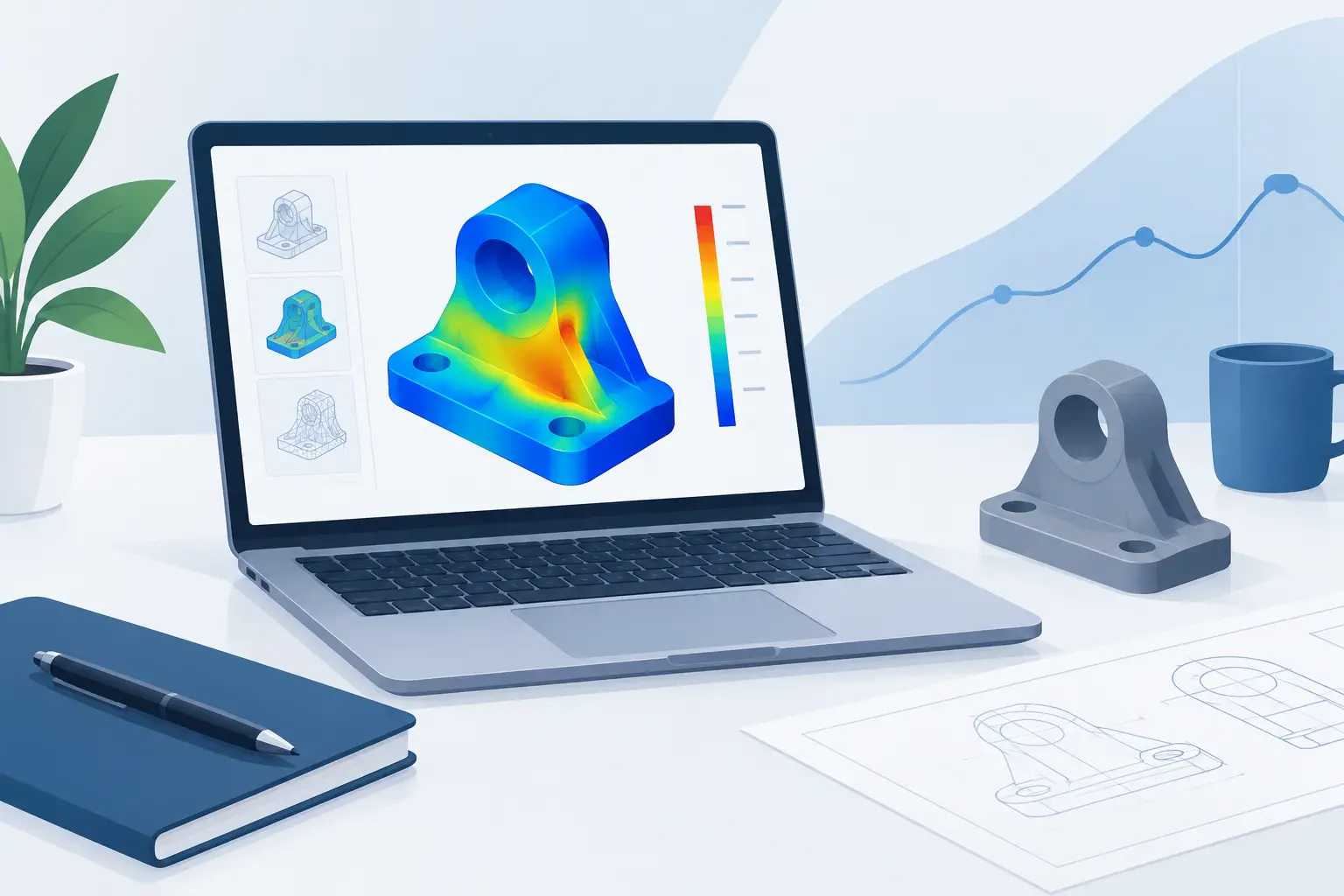
A stress result without its load path, boundary conditions, material basis and units is difficult to trust. The best stress analysis tools do more than produce a peak value or a contour plot: they make the engineering reasoning visible enough to check, communicate and reuse.
For routine design work, the right tool is rarely the one with the most features. It is the one that matches the decision being made. A bolted bracket check, a welded connection assessment and a nonlinear finite element model have different inputs, different failure modes and different review requirements. Treating them as the same type of problem creates either unnecessary modelling effort or unjustified confidence.
What stress analysis tools need to support
Stress analysis starts with a model of reality, not software. Engineers define geometry, loads, restraints, material properties and acceptance criteria, then decide what level of idealisation is appropriate. Software should support that chain of reasoning rather than hide it behind a result.
For many mechanical, civil and structural checks, an analytical calculation is the fastest and clearest method. Beam bending, axial stress, torsion, bearing stress, bolt preload, pressure vessel wall stress and simple deflection checks are often governed by well-established equations. A calculation worksheet can show each input, equation, unit conversion, assumption and utilisation result on one page.
Finite element analysis becomes more appropriate when the geometry, restraint conditions or load distribution makes closed-form equations unreliable. Examples include local stress concentrations, complex frames, contact problems, thin-walled components and assemblies with several stiffness paths. Even then, analytical checks remain essential. They provide an order-of-magnitude comparison for reactions, displacement and nominal stress before detailed results are accepted.
The useful distinction is not between simple and advanced tools. It is between a method that is proportionate to the engineering risk and one that is merely convenient.
The main types of stress analysis tools
A practical workflow usually combines several tool categories rather than relying on one application.
Calculation worksheets for transparent checks
Unit-aware engineering worksheets are suited to repeatable design calculations. They work particularly well where equations are known, assumptions need to be stated, and another engineer must review the result. A worksheet for a cantilever beam, for example, can record the section properties, distributed load, maximum moment, bending stress, allowable stress and deflection limit alongside explanatory notes.
This approach is more controlled than a generic spreadsheet when units and documentation matter. A value entered in millimetres should not be silently combined with a formula expecting metres. Equally, an output should not appear as an unexplained number several tabs away from the input that drives it.
Calculeaf is designed around this format: unit-aware mathematics, readable formulas, notes, plots and printable calculation pages in one browser-based technical document. That makes it useful for checks that need to be both calculated and issued as engineering evidence.
Spreadsheets for flexible internal models
Spreadsheets remain common because they are accessible and adaptable. They can be effective for controlled, familiar calculations with a limited number of inputs. However, their flexibility is also their weakness. Hidden cells, overwritten formulas, copied constants and inconsistent units can make a workbook difficult to audit.
A spreadsheet is not automatically unsuitable for stress work. It needs disciplined structure, named inputs, visible equations, protected logic and a clear revision process. If the calculation will be reused across projects or reviewed by clients, a purpose-built calculation document is often easier to maintain.
Finite element analysis for complex behaviour
FEA tools calculate stress and deformation across a discretised model. They are valuable when local geometry or interaction effects govern the design. The output can reveal load paths that simplified equations cannot capture, but it also introduces model sensitivity.
Mesh density, element type, contact definitions, material nonlinearity and restraints can materially change the result. A high stress at a sharp internal corner may be a genuine design issue, a numerical singularity or both. The contour alone does not answer that question. Engineers need convergence checks, sensible averaging, realistic supports and a defined interpretation of peak stress.
Specialist code-checking software
Some disciplines use tools built around specific standards and component types, such as steel members, reinforced concrete elements, piping systems or pressure equipment. These can accelerate code compliance because the resistance models and load combinations are embedded in the workflow.
The trade-off is transparency. A code-checking result is only useful if the engineer can identify the selected standard edition, design factors, material grade, effective length, load case and governing clause. Exportable calculation evidence matters as much as a pass or fail indicator.
How to choose a stress analysis tool
Start with the decision that the analysis must support. Is the task a quick feasibility check, a detailed design verification, an independent review, or a reportable deliverable? The answer determines the required level of model detail and documentation.
Assess tools against four practical questions:
- Can the tool represent the relevant physics without forcing unnecessary complexity?
- Are inputs, units, formulas and assumptions visible to a reviewer?
- Can the calculation be checked independently using a simplified method?
- Can the final output be reused and issued without rebuilding the documentation elsewhere?
For a simple bracket, a hand-calculation-style worksheet may be the primary analysis, with FEA used only to investigate a local feature. For a cast housing under combined loading, FEA may be primary, supported by free-body diagrams and nominal stress checks. Neither route is inherently better. The governing issue is whether the evidence is sufficient for the consequence of failure.
Build verification into the workflow
The most expensive errors in stress analysis are often modelling errors, not arithmetic errors. A calculation can be numerically correct while describing the wrong load case or restraint condition.
Begin with a free-body diagram. Show the applied loads, directions, reactions and dimensions. Calculate equilibrium before moving to stress. If reactions do not balance, the model is not ready for refinement.
Next, establish a simple benchmark. For an FEA model of a beam-like member, compare the predicted deflection and nominal bending stress against beam theory away from load introduction points and supports. For a bolted joint, compare the distribution of load with an analytical stiffness model. Differences are not necessarily failures, but they should have a physical explanation.
Unit control deserves the same attention. Mixed systems can introduce errors that look plausible, particularly where modulus, pressure, torque and section properties are involved. Use a tool that carries units through formulas where possible, and state any intentional conversions directly in the document.
Finally, distinguish between stress measures. Von Mises stress may be appropriate for assessing yielding in ductile metals, while principal stress may matter for brittle materials, and fatigue assessment requires stress range, mean stress effects and cycle information. A single maximum stress value cannot answer every design question.
Make results reviewable, not merely available
A good analysis package allows a reviewer to reconstruct the argument without opening a meeting or searching through folders. The calculation record should identify the component, revision, material data, design loads, combinations, assumptions, acceptance criteria and result.
For FEA, include model images, mesh information, boundary conditions and a short explanation of how singularities or local peaks were treated. For analytical checks, show the governing equations and define each variable. Where a value comes from a standard, drawing or supplier document, record the source reference in the notes.
This level of documentation is not administrative overhead. It prevents a common failure in engineering teams: a result is retained, but the reasoning behind it is lost. When the load changes, the material is substituted or the geometry is revised, the calculation must be reassessed rather than copied forward on trust.
Choose tools that preserve engineering judgement
Stress analysis software should reduce repetitive work, not replace judgement. Use analytical worksheets to make straightforward checks fast and readable. Use FEA where geometry and behaviour require it. Use code-checking tools where standards-based design is central to the task. Then connect the outputs in a calculation record that another engineer can follow.
The strongest result is not the most colourful contour or the most elaborate workbook. It is a result with a credible model, visible assumptions, consistent units and enough context that the next engineer can decide whether it still applies.