2D structural frames
Use a 2D Frame when the sheet needs member forces it cannot get from a closed-form expression. A portal, a braced bay, a beam with an awkward load pattern.
You sketch the nodes, members, supports, and loads, then press
Solve. Calculeaf runs a linear-elastic plane-frame analysis
with three degrees of freedom per node (ux, uy,
rz).
The answers are not trapped in a picture. Reactions, member forces, deflections, and stresses become named worksheet variables. The rest of the calculation can use them like any other quantity.
Those names enter scope at the frame's own place in evaluation order. Math that uses them must sit below the frame. The variables the frame reads — load magnitudes, section dimensions, Young's modulus — must be defined above it.
Place the region
- On the Insert tab, choose 2D Frame. The ribbon describes it as the region where you sketch members, supports and loads, then solve.
- Click the page. You get an empty frame region: toolbar on top, blank sketch, and the Details panel open on its Selection tab.
- Set Unit and Prefix now if you already know them. Both are easier to fix before there is anything to break.
The status bar underneath the sketch reads Sketch nodes and members, add supports and loads, then Solve. It keeps you posted from then on: the running node and member count, the pointer coordinates while the Node tool is active, a Solved line after a successful run, and the solver error when the model will not stand up.
Unit, Prefix, and Snap
| Control | What it sets |
|---|---|
| Unit | Length unit for sketch coordinates and every distance field: m, mm, cm, ft, or in. Node x and y, member lengths, and load distances are all read in this unit. Changing it later does not convert the coordinates you have already typed. The same numbers are re-read in the new unit, so the model changes size. |
| Prefix | Short identifier prepended to every result name. Up to 16
characters, and it must be a valid variable name. The default is
fr. Give each frame on a sheet its own prefix so their
answers cannot collide. The demo beam below uses ss. |
| Snap | When ticked, node placement snaps to the spacing in the adjacent number field, shown in the current Unit. Untick it to place nodes freely. |
The sketch tools
The first toolbar row holds the six things you do to a frame. Whichever tool you pick stays active until you choose another. You can place a run of nodes without going back to the toolbar.
| Tool | What it does |
|---|---|
| Select | Moves nodes and members. Shift-click a member, or ⌘-click / Ctrl-click , to add members to the selection. Alt-drag, right-drag, or middle-drag pans the view. With Callouts on, clicking a diagram pins a value. |
| Node | Clicking empty space places a joint. Clicking an existing member splits it at that station. The original member becomes two, sharing the new node. |
| Member | Click two nodes to connect them. A rubber band follows the pointer after the first click. |
| Load | Click a node for a joint load (Fx, Fy, M), or a member for a member load, which can be a point load or a UDL. |
| Delete | Click a support symbol to remove that support and leave the node in place. Otherwise it deletes the current selection, whether that is a node, a member, or a load. |
| Solve | Analyses the frame. The region also re-solves on its own when you change a property that affects the model. |
Build the geometry
- Choose Unit — m for a building frame, mm for a detail.
- Set Prefix, for example
ssorportal. - With Node, place the joints. Select each one and give it a Support and a short Label such as A, B, or C. Labels become the suffix on the names Solve writes, so pick them with the formulas below in mind.
- With Member, connect the nodes. Select each member, set its End i and End j releases, and assign a Section.
- On Details → Sections, add a section, set E and the dimensions, then use Apply to selected or Apply to all.
- With Load, click the loaded nodes and members and type the magnitudes.
- Press Solve, tick the overlays you want to see, then press Fit so the whole model sits in the canvas.
- In math below the frame, type the prefix and let autocomplete offer the
names:
ss_RyA =,ss_MmAB =.
Supports
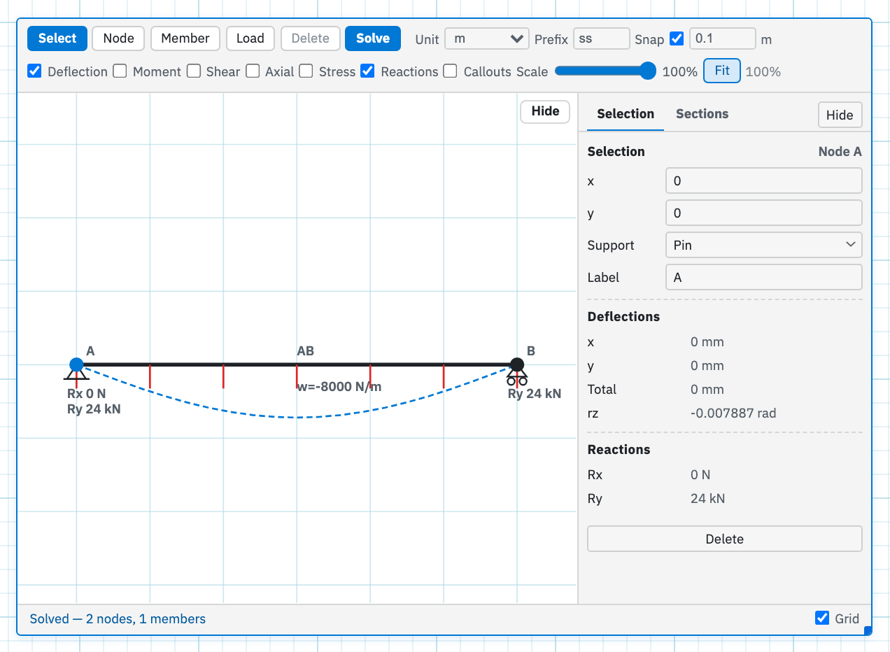
Select a node and Details → Selection gives you its x, y, Support, and Label. The support you choose fixes which of the three degrees of freedom are held.
| Support | Restrained | Free |
|---|---|---|
| Free | none | ux, uy, rz |
| Pin | ux, uy | rz (rotation) |
| Fixed | ux, uy, rz | — |
| Roller | uy (vertical) | ux, rz — a horizontal roller |
| V-roller | ux (horizontal) | uy, rz — a vertical-wall roller |
After a solve the same panel adds Deflections (x, y, Total, and rz) and Reactions. Only the restrained directions get a reaction row, so a pin shows Rx and Ry but no M. Every value in these blocks is a button. Click it to copy the matching variable name to the clipboard, ready to paste into a math region.
Members and their releases
Select a member and the Selection tab offers:
- Label is the suffix on that member's names, so AB
gives
ss_MmAB. - L is read-only. It comes from the two node positions and the current Unit.
- End i and End j are each Fixed, meaning moment-resisting, or Pin, which releases the moment at that end. Pin both ends for a truss bar. Leave both Fixed for a beam-column.
- Section picks from the Sections catalogue. A preview shows A, I, and c, the extreme-fibre distance, as soon as the dimensions are valid.
- Add load attaches a member load without switching to the Load tool.
Shift-click several members to assign one section to all of them in a single move. Once solved, the panel lists peak Forces (Moment, Shear, Axial), Stresses where a section is assigned, and Deflections — each with the station along the member at which the peak occurs. Click that station and the sketch jumps to it with a callout pinned.
A member with no section still solves, using the frame defaults for E, A, and I. What you lose is stress. The stress overlay has nothing to draw on that member, and no stress names are written for it.
Sections
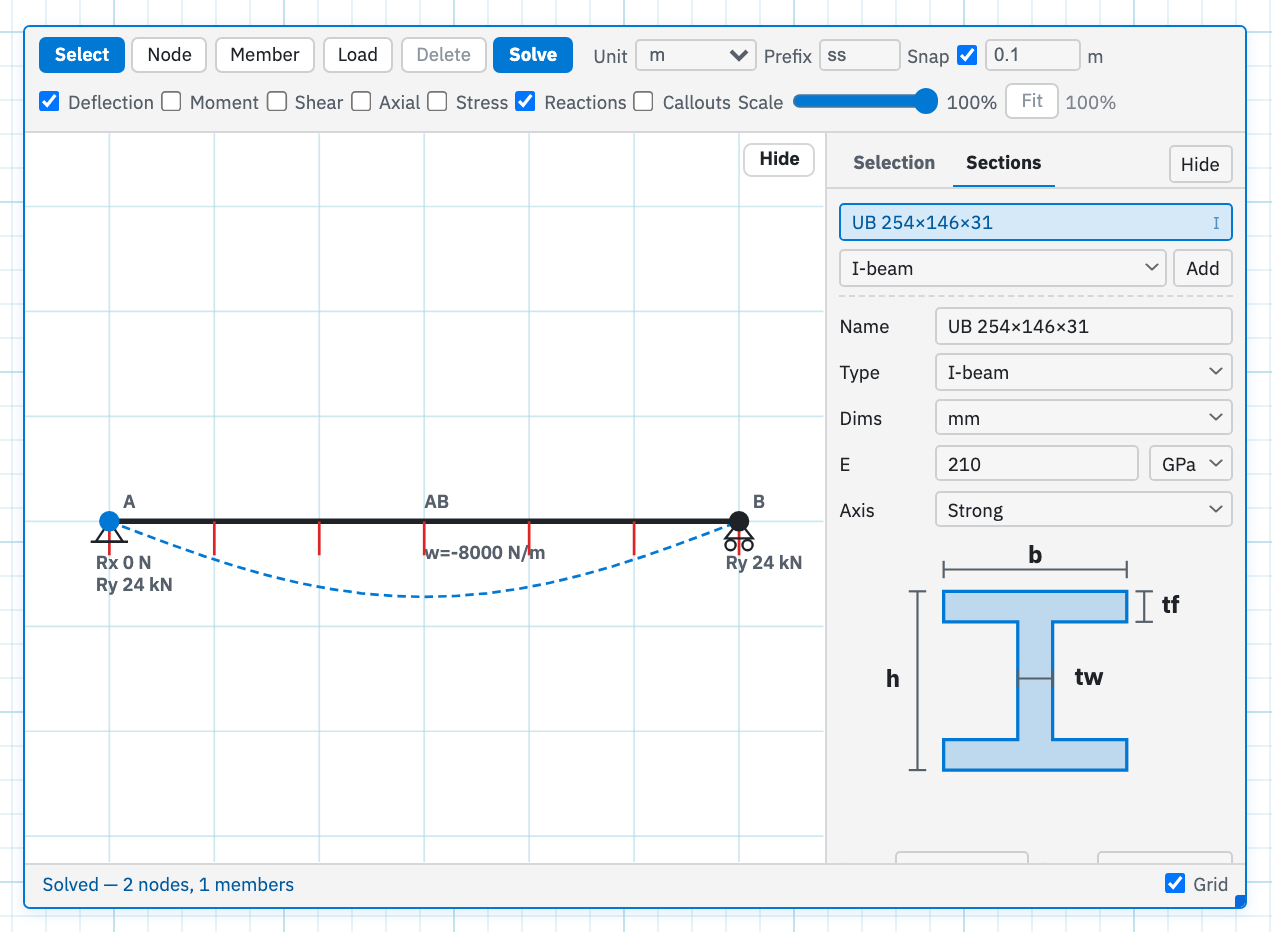
Details → Sections is a catalogue local to this frame. Choose a type, press Add, and edit the section that appears:
- Name is what you see in the list and in the member Section dropdown.
- Colour is the square to the left of each section in the list. Click it to open the same picker as text colour. While the Sections tab is open, members assigned that section draw in that colour so you can see which beams share a catalogue entry. Leave the tab and they return to the usual ink.
- Type is one of I-beam, Square hollow (SHS), Rectangular hollow (RHS), Circular hollow (CHS), Angle, Circular bar, Square bar, Rectangle bar, or Custom.
- Dims sets the unit for the dimension fields — mm, cm, m, in, or ft — independently of the sketch Unit.
- E is Young's modulus, entered as a number or a sheet variable, with a unit of Pa, kPa, MPa, GPa, psi, or ksi.
- Axis appears on I-beam, RHS, and Angle and decides which second moment of area is used in bending. I-beam, RHS, and Rectangle bar offer Strong and Weak. Angle offers Strong, X-X, and Y-Y.
- The dimension fields take numbers or sheet variables, and a diagram labels each one — h, b, tw, tf on an I-beam; B and t on an SHS; and so on.
- The preview line reports A, I, and c once the dimensions resolve.
- Apply to selected and Apply to all assign the section to members without visiting each one.
- Delete section removes it from the catalogue. Members that used it lose the assignment and fall back to the frame defaults.
| Type | Dimensions |
|---|---|
| I-beam | h overall depth, b flange width, tw web, tf flange |
| Square hollow | B outer width, t wall |
| Rectangular hollow | H outer depth, B outer width, t wall |
| Circular hollow | D outer diameter, t wall |
| Angle | d vertical leg, b horizontal leg, t thickness |
| Circular bar | d diameter |
| Square bar | a side |
| Rectangle bar | b width, h depth |
| Custom | A area, I second moment, y to furthest fibre |
Loads
Every magnitude field takes either a number or the name of a sheet variable defined above the frame. That is how you drive a frame from the inputs at the top of the calculation. The sketch Y axis points up, so a downward force or UDL is a negative number.
Nodal load
Click a node with the Load tool. The Selection panel is titled Nodal load.
- Fx and Fy are global components.
- M is an in-plane moment. Its unit follows the force unit: N gives N·m, kN gives kN·m, MN gives MN·m, lbf gives lbf·ft, and kip gives kip·ft.
- Unit is one of N, kN, MN, lbf, or kip.
Member load — Point
Click a member instead and Type lets you choose Point or UDL. A point load has:
- Fx and Fy, again global components.
- From, which end the distance is measured from — end i or end j.
- Dist, the distance from that end, in the frame Unit or as a sheet variable.
- Unit, the same force units as a nodal load.
Member load — UDL
- Dir is either Global Y, the sketch vertical, or Local y, perpendicular to the member.
- From, Start, and End define the loaded segment, measured from the chosen end. Leave Start at 0 and End at the member length for a full-span UDL.
- w1 and w2 are the intensities at Start and End. Equal values give a uniform load. Different values give a trapezoid or a triangle.
- Unit is one of N/m, kN/m, N/mm, lbf/ft, or kip/ft.
Solve, and what to do when it refuses
Solve assembles the stiffness matrix, solves it, and pushes the answers into the worksheet, which then re-evaluates. A model that cannot stand up produces a message in the status bar and no answers at all: Add at least two nodes, Add at least one member, Add at least one support so the frame is stable, or The stiffness matrix is singular — the frame is a mechanism or poorly supported. That last one usually means a missing release, a support that restrains too little, or a member floating unconnected.
Read the answer off the sketch
The second toolbar row controls what is drawn on top of the model after a successful solve.
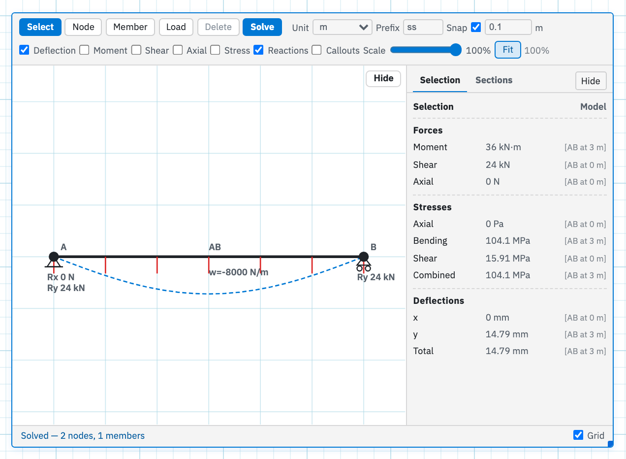
- Deflection draws the displaced shape as a dashed line, and is on by default.
- Moment, Shear, and Axial draw force diagrams along each member. Axial is tension-positive: blue is tension (T), red is compression (C). Details and callouts tag the peak with T or C.
- Stress draws the combined stress diagram. Members without a section have nothing to draw.
- Reactions shows the support arrows and their values, and is on by default.
- Callouts is off by default. Tick it and hovering a moment, shear, axial, stress, or deflection diagram gives a tooltip that tracks the station. Click to pin it, and click a pinned callout to remove that one. Pins are stored with the region.
- Scale is a 20–100% slider for diagram amplitude, covering moment, shear, axial, stress, and deflection.
- Fit frames the whole model in the canvas. Use it after sketching, or when Details is covering a support.
- The zoom readout shows the current camera zoom. Scroll the sketch to zoom. Alt-drag, right-drag, or middle-drag to pan.
Two controls are not on that row. Grid lives on the status bar. Hide on the sketch collapses the toolbar and becomes Tools to bring it back. Details re-opens the side panel after the panel's own Hide has collapsed it.
What Solve writes into scope
Once the frame solves, its names appear in autocomplete for any math below
it. The scheme is {Prefix}_{quantity}{Label} with
exactly one underscore. The label is glued straight onto
the quantity, so a node labelled B gives ss_uyB and never
ss_uy_B. Whole-model peaks use a fixed word where the label
would go. An unlabelled node or member falls back to its internal id.
Anything in a label that is not a letter, digit, or underscore becomes an
underscore, and the name is trimmed to 20 characters.
Whole-model peaks
| Name | Meaning | Unit |
|---|---|---|
{p}_dmax | Peak resultant deflection | m |
{p}_Mmax | Peak bending moment | N·m |
{p}_Vmax | Peak shear | N |
{p}_Nmax | Peak |axial| force | N |
{p}_axmax | Peak axial stress | Pa |
{p}_bmax | Peak bending stress | Pa |
{p}_tmax | Peak shear stress | Pa |
{p}_smax | Peak combined stress | Pa |
Per node, shown for label A
| Name | Meaning |
|---|---|
{p}_uxA, {p}_uyA, {p}_rzA | Displacement and rotation |
{p}_RxA, {p}_RyA, {p}_RmA | Reactions, written only if the node is restrained |
Per member, shown for label AB
| Name | Meaning |
|---|---|
{p}_NAB, {p}_VAB | Axial (tension positive) and shear at end i |
{p}_MiAB, {p}_MjAB | Moments at ends i and j |
{p}_NmAB, {p}_VmAB, {p}_MmAB | Peak |axial|, shear, and moment on the member |
{p}_dxAB, {p}_dyAB, {p}_dAB | Peak |ux|, peak |uy|, and peak resultant deflection |
{p}_axAB, {p}_bAB, {p}_tAB, {p}_sAB | Peak axial, bending, shear, and combined stress |
Take the demo beam: Prefix ss, a pin at A, a roller at B, a
6 m span, and a UDL of −8 kN/m on member AB. Four math regions below the
frame give you the whole check.
ss_RyA =
ss_RyB =
ss_MmAB =
ss_dmax =
Each reaction comes back as 24 kN, half the 48 kN total.
ss_MmAB comes back as 36 kN·m, which is the wL²/8 you would
expect for a simply supported span. Display units follow the sheet
unit system. SI moves to kN and mm
when values get large or small. USCS uses lbf, kip, and inches. You can
pin a display unit on the answer chip exactly as on any math region.
The frame as part of the sheet
A frame is a region, and it takes part in Evaluate All at its own
order and position. Loads and section dimensions that reference
sheet variables read them from scope above the frame. The answers are
available to everything below it, including as the output of a
plot sweep or a
sweep table.
Copy and paste the region like any other block. The Prefix, the sections, and the pinned callouts travel with it, so remember to change the Prefix on the copy. Deleting a frame removes both the sketch and its names from the next evaluate.
Next, put the math that reads ss_* names
below the frame on the page.