3D structural frames
Use a 3D Frame when the structure does not lie in one plane. A space frame, a corner portal with a roof beam, a cantilever that also bends out of plane.
The editor is the same family as
2D Frame: Node, Member, Load,
Sections, Solve. The extra work is in space. Each node has x,
y, and z. The solver is a linear-elastic space
frame with six degrees of freedom per node
(ux, uy, uz,
rx, ry, rz).
Answers still become worksheet names. Math that reads them must sit below the region in evaluation order. Loads, section sizes, and Young's modulus must be defined above it.
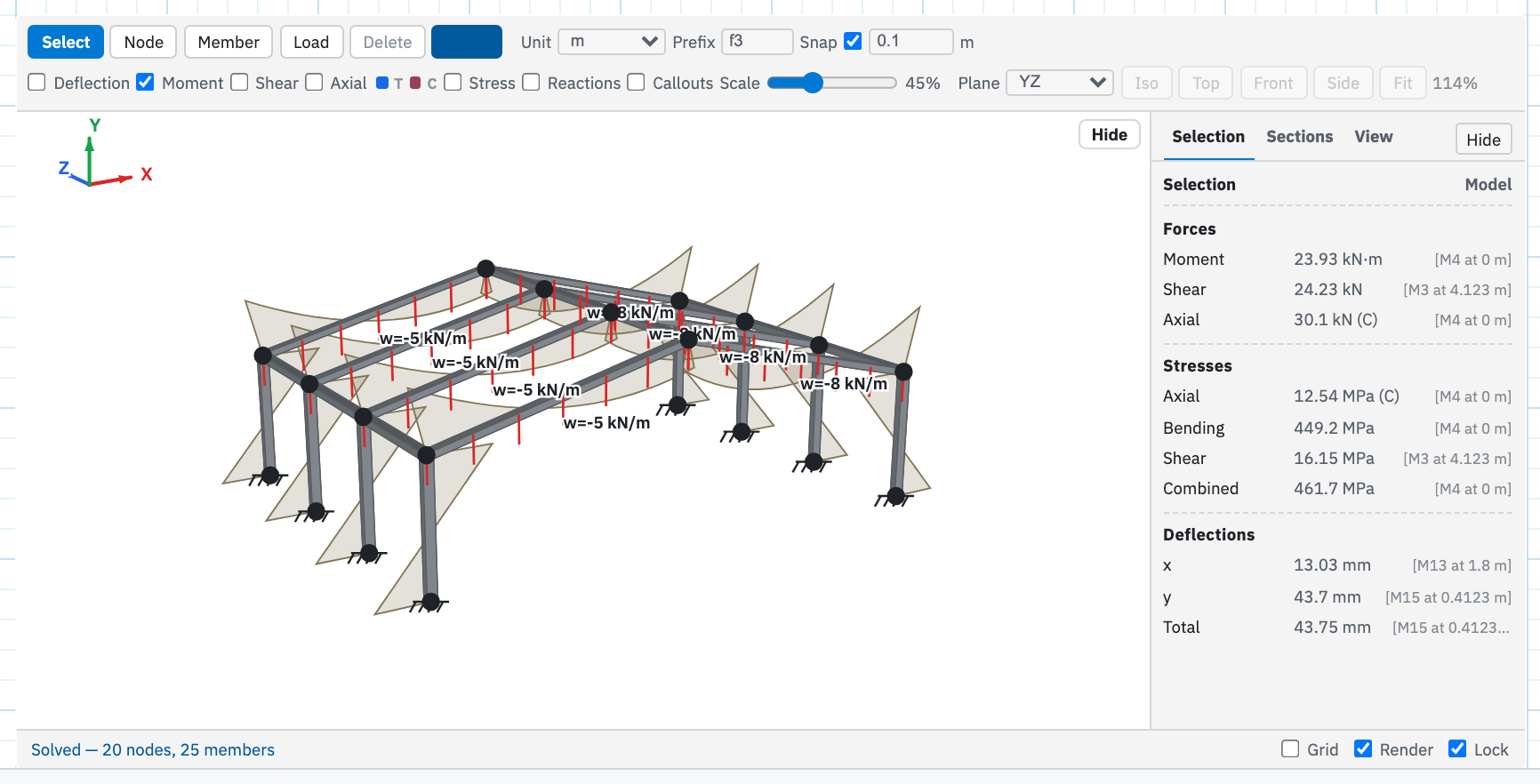
Place the region
- On the Insert tab, choose 3D Frame.
- Click the page. You get the same chrome as 2D: tools on top, sketch in the middle, Details on the right. The camera starts front-on, looking at the XY plane, so the first sketch matches a 2D elevation.
- Set Unit and Prefix before the first
Solve. The default prefix is
f3, so it will not collide with a 2D frame that still usesfr.
Unit, Prefix, and Snap
mean the same as in 2D. Changing Unit later does not convert coordinates you
have already typed. Rename Prefix before you write
f3_RyA into a formula, or that formula keeps pointing at a name
that no longer exists.
Orbit, pan, and zoom
The camera is a view change only. It does not move nodes. Placement always happens on the working plane, not on the camera.
| Gesture | What it does |
|---|---|
| Left-drag empty space (Select tool) | Orbit around the frame. A click with no drag clears the selection; dragging keeps it. The axes triad in the sketch shows X red, Y green, Z blue. Y is up, matching the 2D elevation. |
| Alt-drag, right-drag, or middle-drag | Pan. Same as 2D. |
| Scroll or pinch | Zoom toward the pointer. |
| Iso, Top, Front, Side | View presets. Front is the 2D elevation: looking along −Z. |
| Fit | Frame the model in the view without changing the orbit angles. |
Lock on the frame status bar, next to Grid and Render, freezes that camera. Pan, zoom, orbit, and the view presets stay put, so a composed picture does not jump while you select nodes. It is a camera lock, not the worksheet format lock.
Working plane
Nodes and loads are placed on one plane at a time: XY, XZ, or YZ. The Plane menu sits on the second toolbar row. The status bar names the plane and the locked coordinate, for example XY at z = 0 or YZ at x = −4.
Select a node, then switch plane. The locked coordinate jumps to that node, so the next joint you place stays in the plane through the selection. Sketch a portal on XY, select a top node, switch to XZ, and draw the beam that leaves the plane.
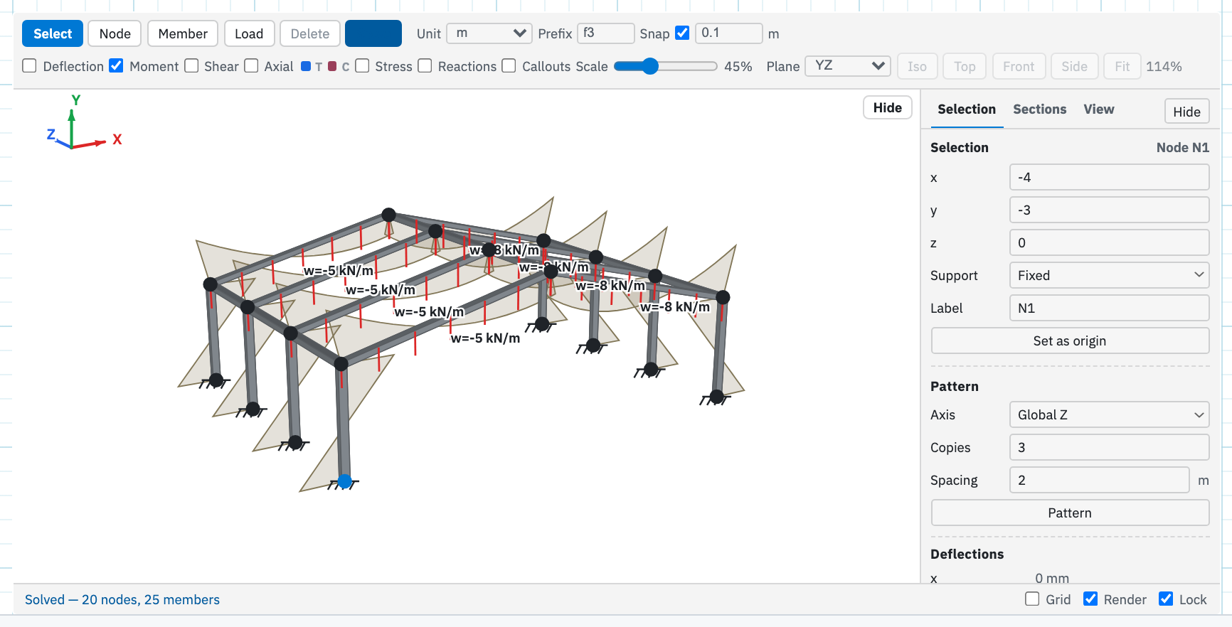
You can still type x, y, and
z in Details for an exact point. Dragging a node keeps it
on the current plane through that node. Set as origin
shifts the whole model so that node is (0, 0, 0). The red,
green, and blue axes sit at that origin.
Pattern
⌘-click or Shift-click to add nodes and members to the selection. Details then shows Pattern: an axis, how many extra copies, and a spacing. Pattern copies the selection along global X, Y, or Z. If a copied node lands on a joint that is already there, that joint is reused and the new beam connects to it instead of stacking a second node.
Copies is the number of extras, not counting the selection. A bay 2 m deep with Copies 3 along Z gives you three more bays, 2 m apart.
Section rotation
I-beams, RHS, and rectangle bars have a strong axis and a weak axis. Select one or more members with ⌘-click or Shift-click, then Rotate 90° in Details. That turns the section about the member axis so gravity sees the other second moment of area. Members that share a catalogue section can still be rotated independently. Turn Render on to see the flanges and web follow. The Axis control on the Sections tab is the catalogue default for that shape; rotation on the member is extra.
View and Render
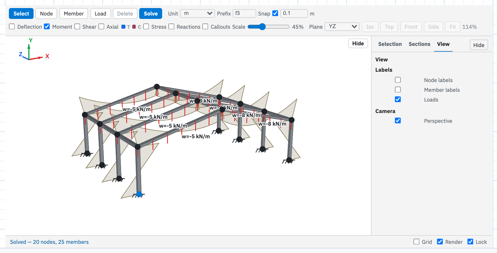
Next to Selection and Sections is View. Turn node and member labels off when the sketch is crowded, or hide Loads so arrows do not cover the members. Perspective foreshortens the camera; the working plane and tools stay the same. Leave it off for a 2D-style elevation.
Render, next to Grid on the status bar, draws each member as its section — I, tube, angle, and the rest — in steel grey. Open the Sections tab and those solids take the catalogue colour. Members without a complete section stay as lines.
The sketch tools
Select, Node, Member, Load, Delete, and Solve are the same six tools as 2D. Node still splits a member if you click it. Load still clicks a node for a joint load or a member for a member load. The 2D page walks through building a model with those tools; the differences in 3D are the plane, the extra support types, and the extra load components.
Supports
Select a node. Details → Selection gives you x, y, z, Support, and Label. The support you choose fixes which of the six degrees of freedom are held.
| Support | Restrained | Free |
|---|---|---|
| Free | none | ux, uy, uz, rx, ry, rz |
| Pin | ux, uy, uz, rx (torsion) | ry, rz — a single beam cannot spin about its axis |
| Fixed | all six | — |
| Roller | uy, uz | ux, rx, ry, rz — a planar beam cannot fall sideways |
| X-roller | ux | everything else |
| Z-roller | uz | everything else |
After a solve the same panel adds Deflections and Reactions. Only the restrained directions get a reaction row. Every value in those blocks is a button. Click it to copy the matching variable name to the clipboard.
Loads
Every magnitude field takes either a number or the name of a sheet variable defined above the frame. Y points up, so a downward force or UDL is a negative number, the same as 2D.
- Nodal load. Fx, Fy, Fz and Mx, My, Mz. The moment unit follows the force unit: kN gives kN·m, lbf gives lbf·ft.
- Member point load. Fx, Fy, Fz, plus From and Dist measured from end i or end j in the frame Unit.
- Member UDL. Dir is Global X, Y, or Z, or local y or z of the member. Start, End, w1, and w2 define a uniform, trapezoid, or triangle load along a segment of the member.
A pin end on a member releases both bending planes (ry and rz), the 3D version of a 2D pin release. Pin both ends for a truss bar.
Solve, overlays, and Sections
Solve assembles the stiffness matrix and pushes the answers into the worksheet. A model that cannot stand up produces a message in the status bar and no names at all. The overlay row is the same as 2D: Deflection, Moment, Shear, Axial (tension blue, compression red), Stress, Reactions, Callouts, and Scale.
Sections are the same catalogue: I-beam, SHS, RHS, CHS, Angle, bars, or Custom, with E and dimensions as numbers or sheet variables. Open 2D structural frames for the dimension table, Apply to selected, and the callout workflow.
What Solve writes into scope
Names follow {Prefix}_{quantity}{Label} with exactly one
underscore, the same scheme as 2D. The default prefix is f3.
Whole-model peaks
(f3_dmax, f3_Mmax, f3_Vmax,
f3_Nmax, f3_smax, and the stress peaks) are
unchanged. In 3D you also get the out-of-plane terms.
Per node, shown for label A
| Name | Meaning |
|---|---|
{p}_uxA, {p}_uyA, {p}_uzA | Translations |
{p}_rxA, {p}_ryA, {p}_rzA | Rotations |
{p}_RxA, {p}_RyA, {p}_RzA | Force reactions, written if a translation is restrained |
{p}_RmxA, {p}_RmyA, {p}_RmA | Moment reactions (Rm is Mz), written if a rotation is restrained |
Per member, shown for label AB
| Name | Meaning |
|---|---|
{p}_NAB, {p}_VAB, {p}_MiAB, {p}_MjAB | Axial, shear, and end moments, as in 2D |
{p}_NmAB, {p}_VmAB, {p}_MmAB | Peak |axial|, shear, and moment on the member |
{p}_dxAB, {p}_dyAB, {p}_dzAB, {p}_dAB | Peak |ux|, |uy|, |uz|, and peak resultant deflection |
{p}_axAB, {p}_bAB, {p}_tAB, {p}_sAB | Peak axial, bending, shear, and combined stress |
A math region below the frame can then read the peaks without picking a particular joint:
f3_smax =
f3_dmax =
f3_RyA =Next, the 2D page for the Sections catalogue and overlay detail, or evaluation order if a name is not defined when you expected it to be.